My RISC-V finally running in university, thank you to all team members

Quantr Foundation Achievements 2023
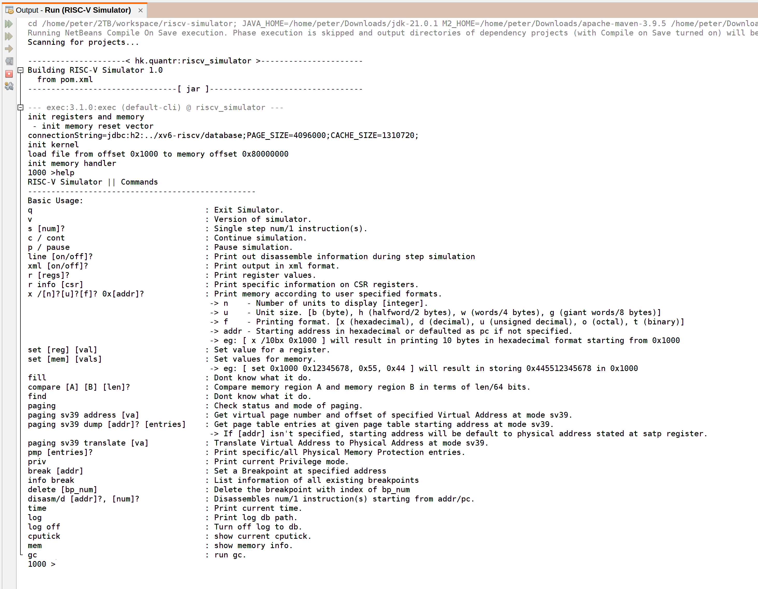
RISC-V Simulator
RISC-V is an open and free instruction set architecture (ISA) that supports various types of computing devices, from embedded systems to supercomputers. RISC-V has many advantages over proprietary ISAs, such as lower cost, flexibility, and innovation. However, RISC-V also faces some challenges, such as the lack of standardization, compatibility, and optimization.
To address these challenges, Quantr Foundation, a non-profit organization dedicated to promoting RISC-V education and development, has created a RISC-V simulator that can help developers and learners to design, test, and debug RISC-V based systems. The Quantr RISC-V simulator is a Java-based tool that can run RISC-V assembly programs and display the execution on different microarchitectures, such as single-cycle and pipelined. The simulator also supports the V extension, which adds vector-based SIMD capabilities to RISC-V, enabling faster and more efficient processing of tasks like media, graphics, and machine learning.
The Quantr RISC-V simulator is not only a useful tool for RISC-V enthusiasts, but also a platform for innovation and collaboration. The simulator is open-source and allows users to add custom fields, transform, merge, trim, and encrypt sections of the executable file format, and optimize the performance and security of the system. The simulator also integrates with other RISC-V projects, such as the QtRVSim, a graphical user interface for the simulator, and the Quantr RISC-V executable file format (.QR), a new format specially designed for RISC-V assembled files.
The Quantr RISC-V simulator is a valuable contribution to the RISC-V community, as it demonstrates the potential and possibilities of RISC-V as a universal ISA for the future of computing. By providing a user-friendly and powerful simulator, Quantr Foundation hopes to inspire more people to join the RISC-V movement and create a more diverse and inclusive computing ecosystem.
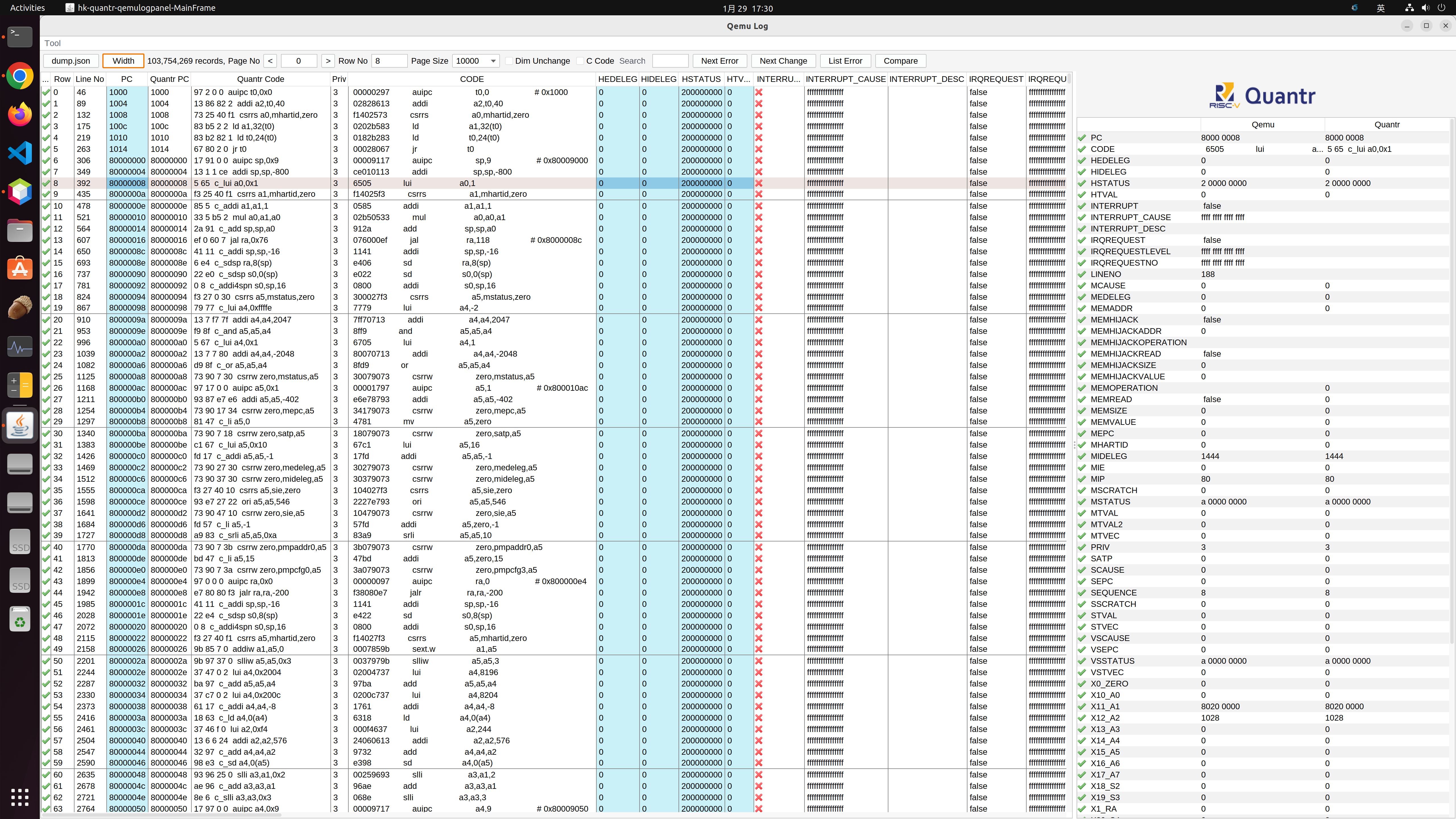
QEMU Log Panel
QEMU is a popular open-source emulator that can run various operating systems and architectures on a single host machine. QEMU is widely used for CPU development, as it allows developers to test their code on different platforms without the need for physical hardware. However, QEMU also generates a large amount of log data, which can be difficult to analyze and debug.
To solve this problem, Quantr Foundation, a non-profit organization that promotes RISC-V education and development, has created a QEMU log panel, a software tool that can help developers and learners to analyze the log generated by QEMU. The QEMU log panel is a Java-based tool that can convert the QEMU log into an H2 database, which can be queried and manipulated using SQL commands. The QEMU log panel also provides a graphical user interface (GUI) that can display the log data in a table format, and allow users to compare the log data from different sources, such as xv6-riscv, a simple Unix-like operating system for RISC-V, and Quantr’s own RISC-V simulator.
The QEMU log panel is not only a useful tool for QEMU users, but also a platform for learning and innovation. The QEMU log panel is open-source and allows users to customize and extend its functionality, such as adding new fields, transforming, merging, trimming, and encrypting sections of the executable file format, and optimizing the performance and security of the system. The QEMU log panel also integrates with other RISC-V projects, such as the Quantr RISC-V executable file format (.QR), a new format specially designed for RISC-V assembled files, and the Quantr RISC-V simulator, a Java-based tool that can run RISC-V assembly programs and display the execution on different microarchitectures.
The QEMU log panel is a valuable contribution to the QEMU and RISC-V communities, as it demonstrates the power and potential of QEMU as a versatile emulator for CPU development. By providing a user-friendly and powerful log analyzer, Quantr Foundation hopes to inspire more people to join the QEMU and RISC-V movements and create a more diverse and inclusive computing ecosystem.
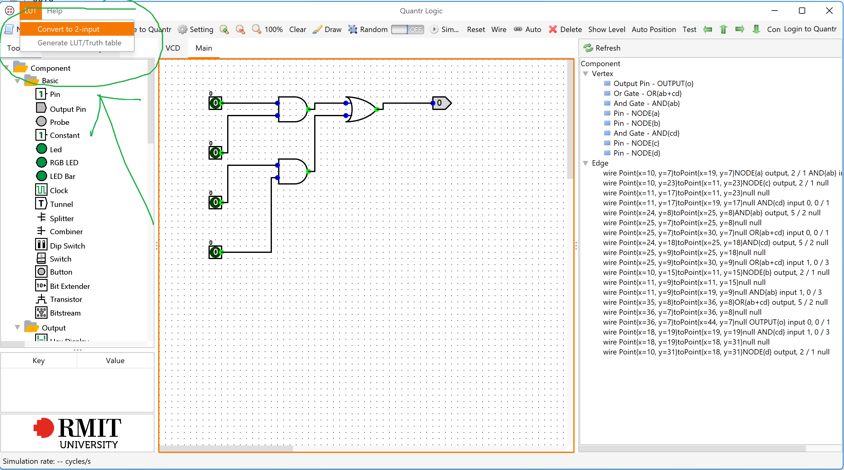
Quantr Logic – Circuit simulator
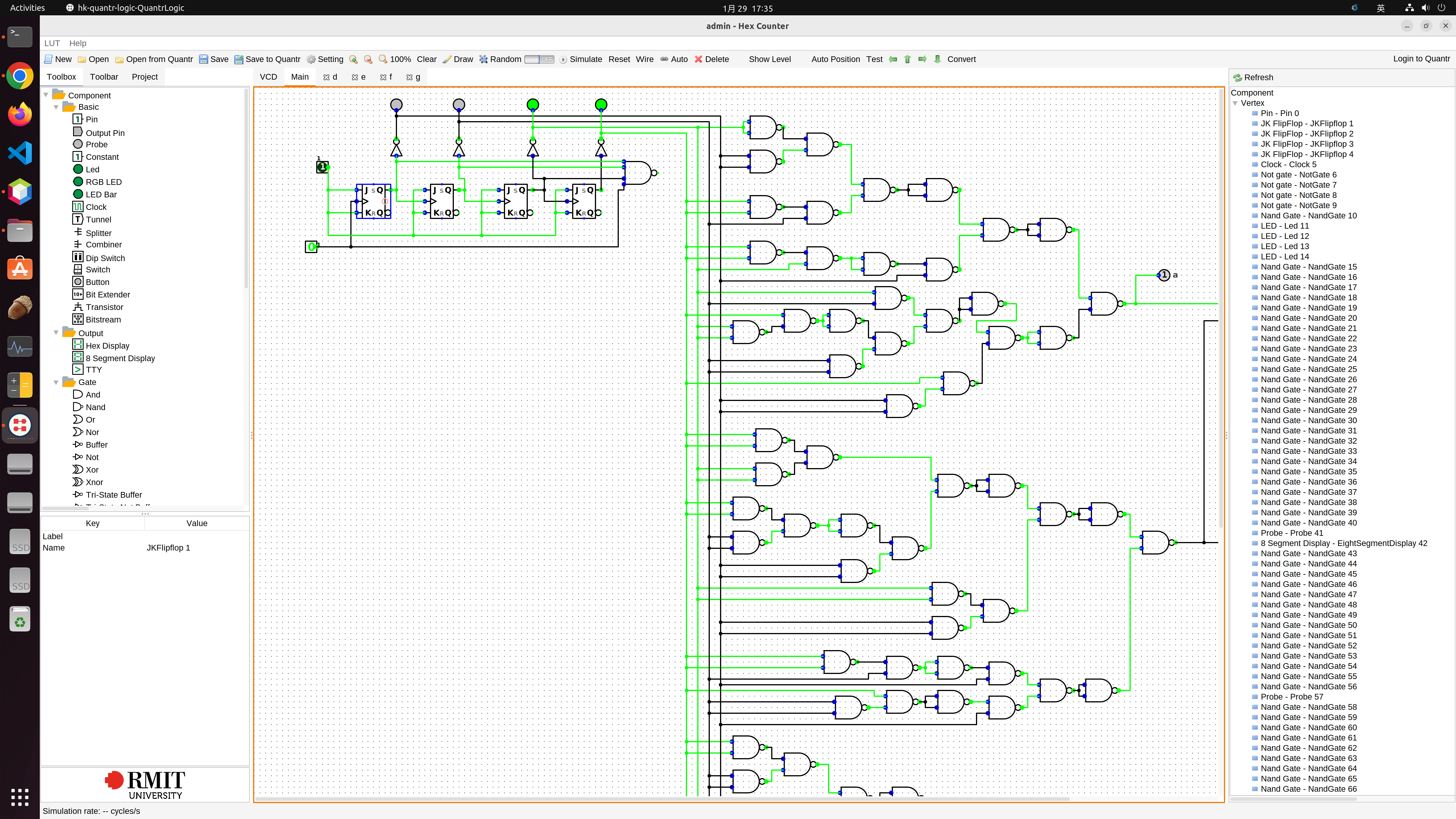
Quantr Logic is a circuit simulator that can help developers and learners to design, test, and debug digital logic circuits. Quantr Logic is a web-based tool that can run on any browser and device, without the need for installation or registration. Quantr Logic is developed by Quantr Foundation, a non-profit organization dedicated to promoting RISC-V education and development.
Quantr Logic allows users to create and edit circuits using a drag-and-drop interface, and provides a variety of components, such as gates, flip-flops, multiplexers, decoders, and registers. Quantr Logic also supports the creation of custom components, which can be reused and shared with other users. Quantr Logic can simulate the circuits in real-time, and display the values of the inputs, outputs, and internal signals. Quantr Logic also provides a waveform viewer, which can show the changes of the signals over time, and a truth table generator, which can show the logical relations between the inputs and outputs.
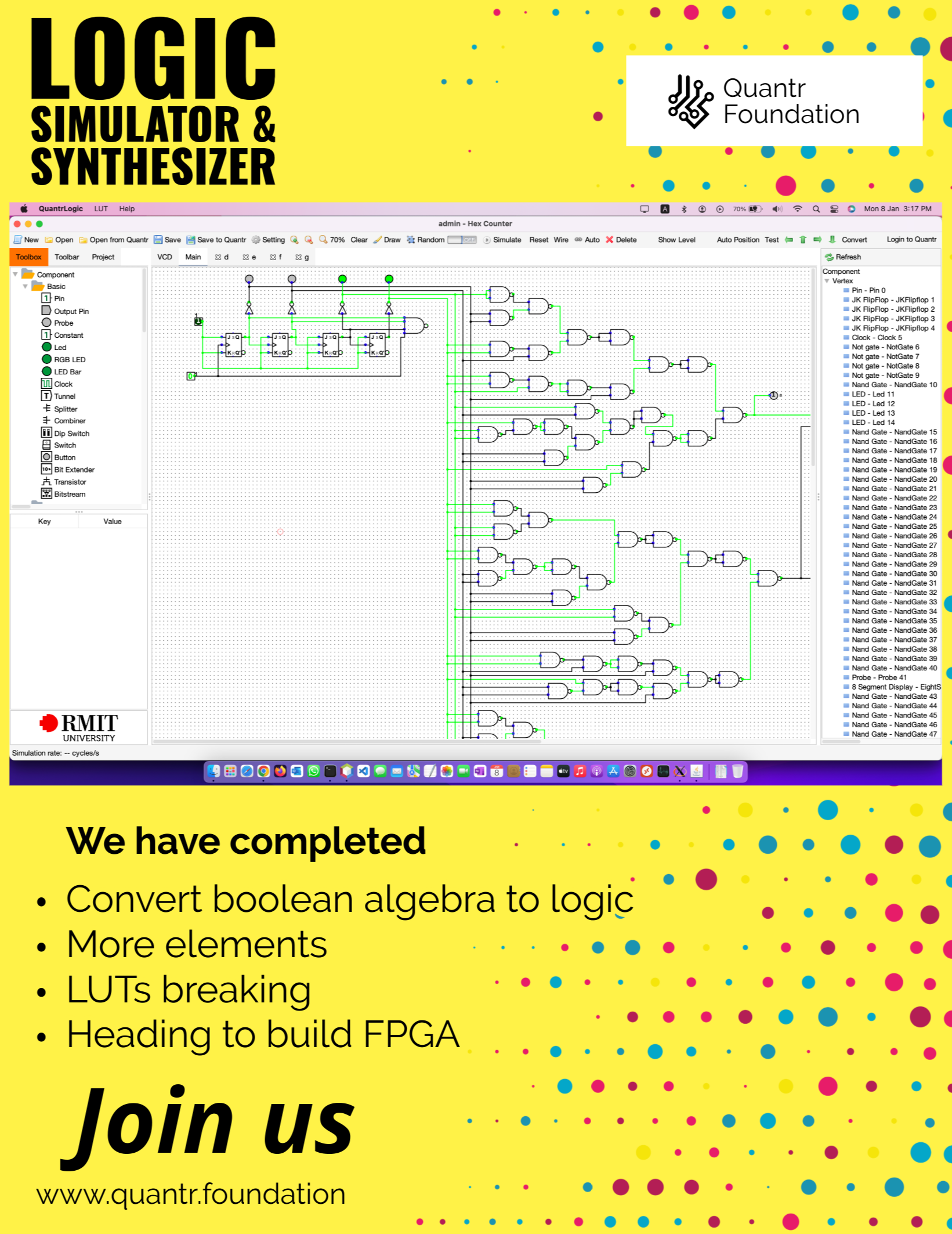
Quantr Logic is not only a useful tool for circuit design, but also a platform for learning and innovation. Quantr Logic is open-source and allows users to contribute to its development and improvement. Quantr Logic also integrates with other RISC-V projects, such as the Quantr RISC-V executable file format (.QR), a new format specially designed for RISC-V assembled files, and the Quantr RISC-V simulator, a Java-based tool that can run RISC-V assembly programs and display the execution on different microarchitectures.
Quantr Logic is a valuable contribution to the circuit design and RISC-V communities, as it demonstrates the power and potential of digital logic circuits as the building blocks of computing systems. By providing a user-friendly and powerful circuit simulator, Quantr Foundation hopes to inspire more people to join the circuit design and RISC-V movements and create a more diverse and inclusive computing ecosystem.
What we do in 2024

The Hong Kong CPU Project is an open source project initiated by Hong Kong people to design and manufacture a central processing unit (CPU) based on the RISC-V architecture. RISC-V is a free and open instruction set architecture (ISA) suitable for various types of computing devices, from embedded systems to supercomputers. RISC-V has many advantages over other proprietary ISAs, such as low cost, flexibility and innovation. The Hong Kong people’s CPU project hopes to use the advantages of RISC-V to create a CPU suitable for Hong Kong people and at the same time promote the development of computer technology in Hong Kong.
Hong Kong’s CPU project covers all stages of CPU design, simulation, verification, compilation, testing and manufacturing. The plan uses a variety of open source tools and platforms, such as QEMU, CPU-Z, Computer and Communication Products Recycling Program, etc. The plan also cooperates with other RISC-V projects, such as Quantr Foundation’s RISC-V simulator, RISC-V executable file format (.QR), QtRVSim, etc. The result of the project is a CPU called HKCPU, which uses the 32-bit RISC-V ISA and supports V extensions, the vectorized SIMD function, which can speed up and improve the efficiency of processing tasks such as media, imaging and machine learning.
The Hong Kong people’s CPU project is a valuable contribution, showing the creativity and ability of Hong Kong people to the world. By providing a user-friendly and powerful CPU, Hong Kong’s CPU Project hopes to inspire more Hong Kong people to participate in the RISC-V movement, while creating a more diverse and inclusive ecosystem for Hong Kong’s computer technology.

香港人嘅cpu計劃是一個由香港人發起嘅開源計劃,目的係為咗設計同製造一個基於RISC-V架構嘅中央處理器(CPU)。RISC-V係一個自由同開放嘅指令集架構(ISA),適用於各種類型嘅計算設備,由嵌入式系統到超級電腦。RISC-V相比其他專有嘅ISA,有好多優勢,例如低成本、靈活性同創新性。香港人嘅cpu計劃希望利用RISC-V嘅優勢,打造一個適合香港人嘅CPU,同時推動香港嘅計算機科技發展。
香港人嘅cpu計劃涵蓋咗CPU嘅設計、模擬、驗證、編譯、測試同製造等各個階段。計劃採用咗多種開源嘅工具同平台,例如QEMU、CPU-Z、電腦及通訊產品回收計劃等。計劃亦同其他RISC-V嘅項目有合作,例如Quantr Foundation嘅RISC-V模擬器、RISC-V執行檔格式(.QR)、QtRVSim等。計劃嘅成果係一個名為HKCPU嘅CPU,佢採用咗32位元嘅RISC-V ISA,支援V擴展,即向量化SIMD功能,可以加快同提高處理媒體、圖像同機器學習等任務嘅效率。
香港人嘅cpu計劃係一個有價值嘅貢獻,向世界展示咗香港人嘅創意同能力。通過提供一個用戶友好同強大嘅CPU,香港人嘅cpu計劃希望激勵更多香港人參與RISC-V嘅運動,同時為香港嘅計算機科技創造一個更多元同包容嘅生態系統。
All our swing projects use this class to serialize settings into XML, back and forth. It is quite convenient but if we create an annotation for this, it would be even better because we can automate the load/save code. Here is the proposal:
This save the variable x into xml call <classname-x>
@save
public int x;
This save the variable into xml call <my_x>
@save(name=my_x)
public int x;
The xml by default call “setting.xml”, unless specify
@save(name=my_x, file=mySetting.xml)
public int x;
package hk.quantr.qemulogpanel;

import java.io.File;
import java.io.FileInputStream;
import java.io.FileOutputStream;

import org.apache.commons.io.IOUtils;

import com.thoughtworks.xstream.XStream;
import java.io.FileNotFoundException;

public class Setting {

	private static Setting setting = null;
	public static File file = new File("setting.xml");
	public int x;
	public int y;
	public int width;
	public int height;
	public int dividerLocation;

	public String compareDialog_from;
	public String compareDialog_to;
	public String compareDialog_limit;
	public String compareDialog_qemu;
	public String compareDialog_quantr;

	public Setting() {
		width = 800;
		height = 600;
	}

	public static Setting getInstance() {
		if (setting == null) {
			setting = load();
		}
		return setting;
	}

	public void save() {
		XStream xstream = new XStream();
		xstream.alias("Setting", Setting.class);
		String xml = xstream.toXML(this);
		try {
			IOUtils.write(xml, new FileOutputStream(file));
		} catch (Exception e) {
			e.printStackTrace();
		}
	}

	public static Setting load() {
		try {
			XStream xstream = new XStream();
			xstream.allowTypes(new Class[]{Setting.class});
			xstream.alias("Setting", Setting.class);
			Setting s = (Setting) xstream.fromXML(new FileInputStream(file));
			return s;
		} catch (FileNotFoundException ex) {
			ex.printStackTrace();
			file.delete();
			setting = new Setting();
			setting.save();
			return setting;
		}
	}

}
After doing much online research and reading many reference books, our team has figured out a way to convert logic circuits into look-up tables (LUT).
Overview
To convert a logic circuit into LUTs, first we should convert them to 2-input logic gates. The decomposition could only be done with two or fewer input logic gates. After that, we have to convert the diagram to a reduced ordered binary decision diagram (ROBDD). Thus, breaking down the logic circuit into the desired number of inputs in the LUT.
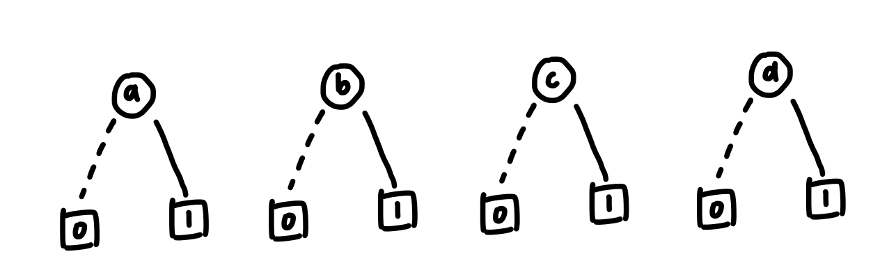
For converting the boolean algebra into a binary decision diagram (BDD), there are certain formulas for converting different logic gates. We could compose the boolean algebra with AND gates, OR gates, XOR gates, and NOT gate. They are listed below:
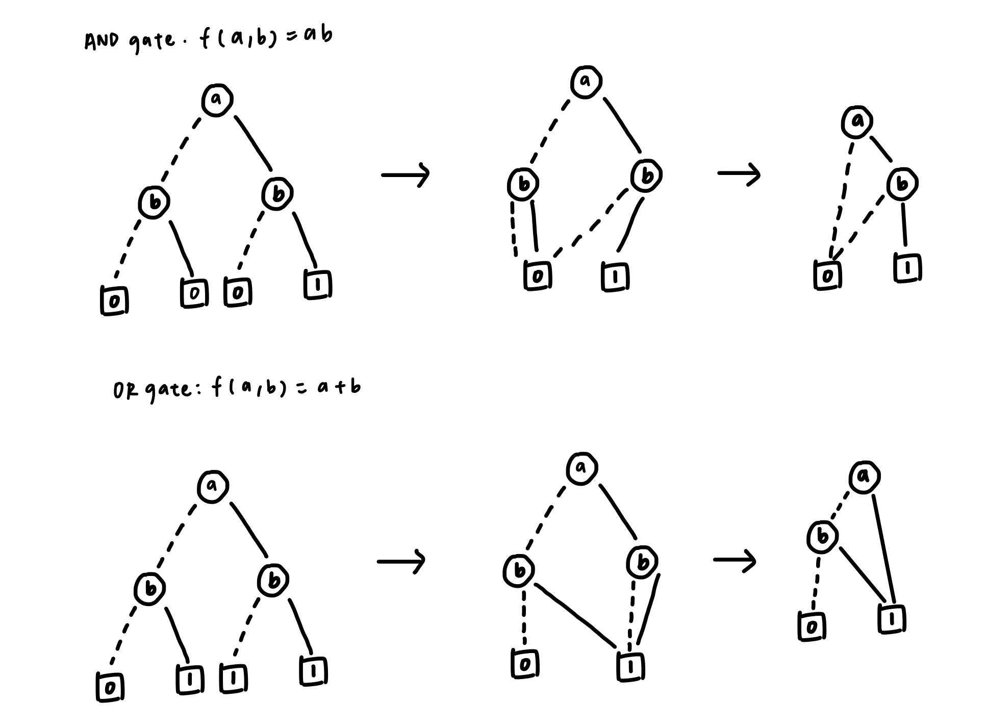
Fig 1. Convert boolean algebra (or , and) to BDD and BDD to ROBDD
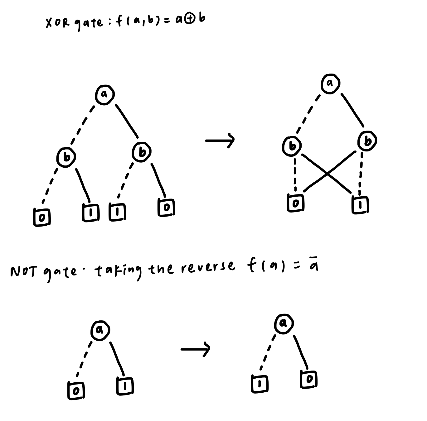
Fig 2. Convert boolean algebra (xor, not) to BDD and BDD to ROBDD
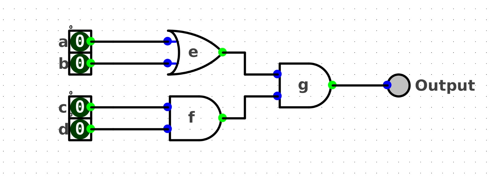
To illustrate how to do the decomposition, here is a simple example:
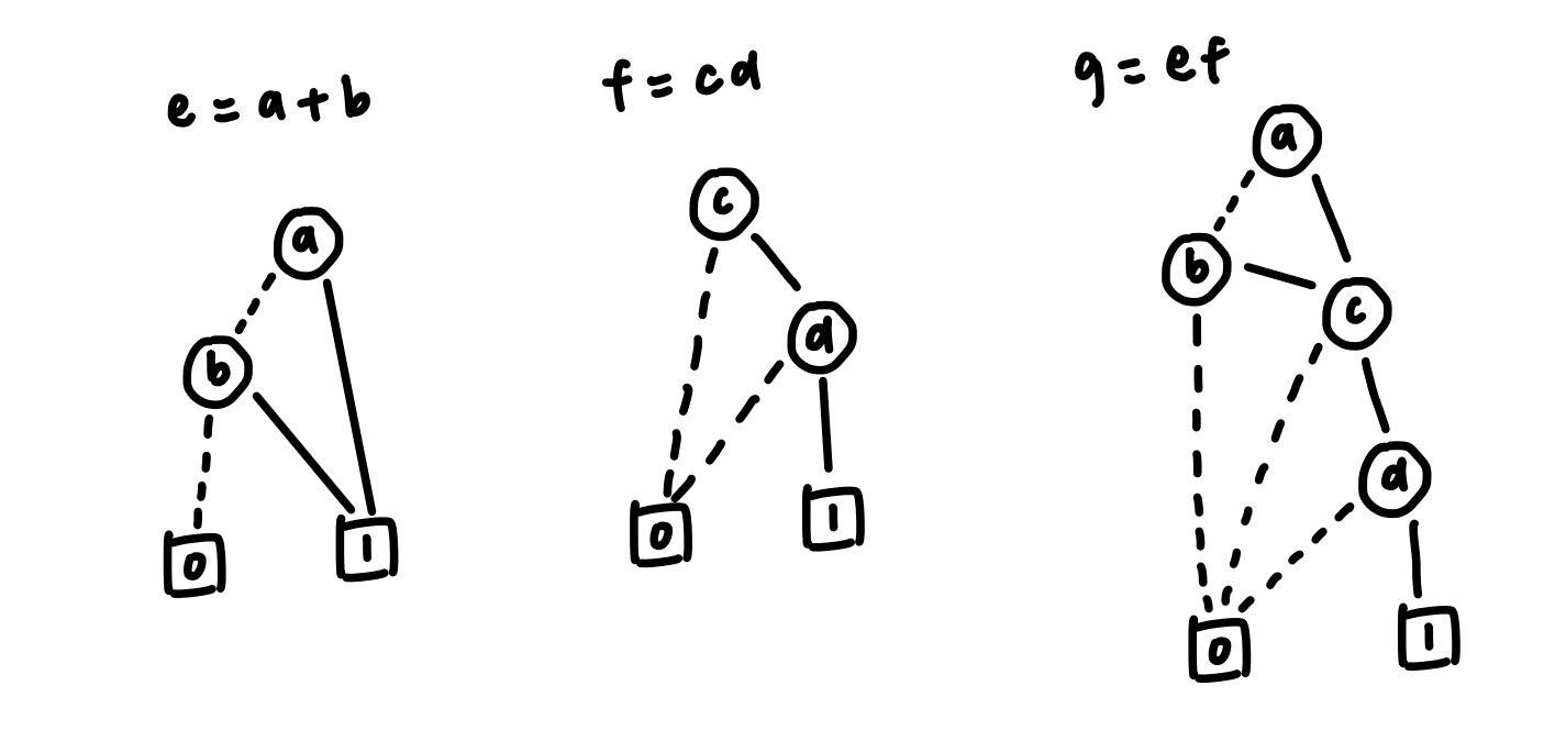
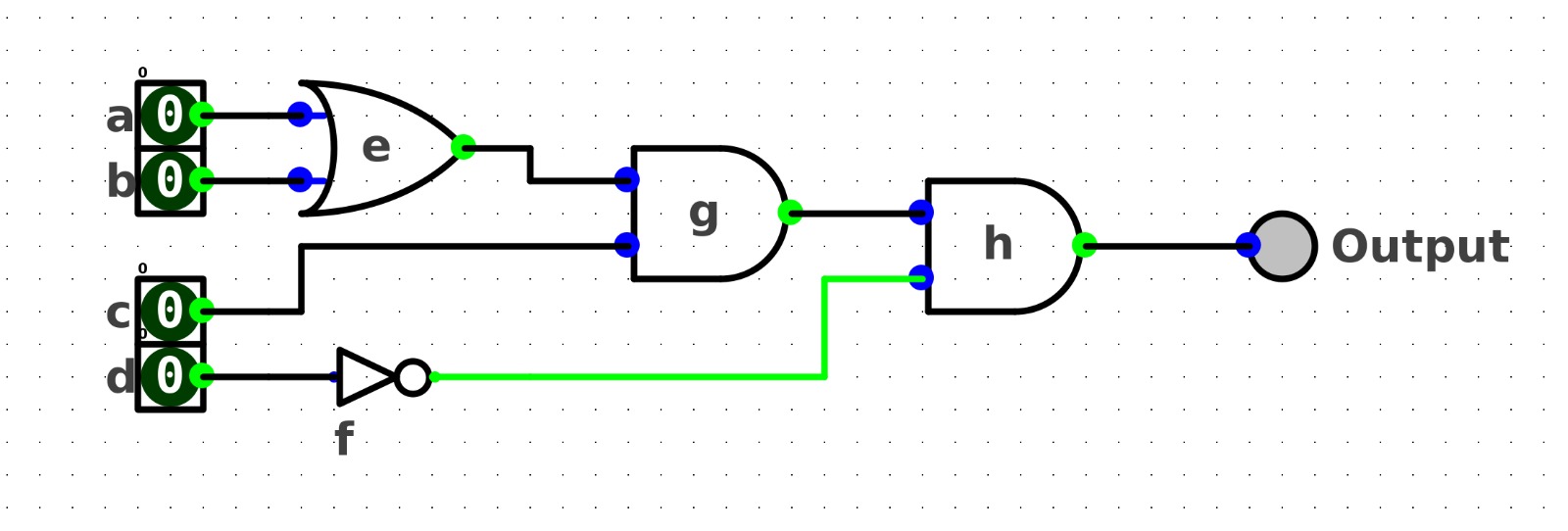
Convert the boolean algebra below into a 3-input LUT circuit.f(a, b, c, d) = (a+b)•cdThe logic circuit of the above boolean algebra looks like this:
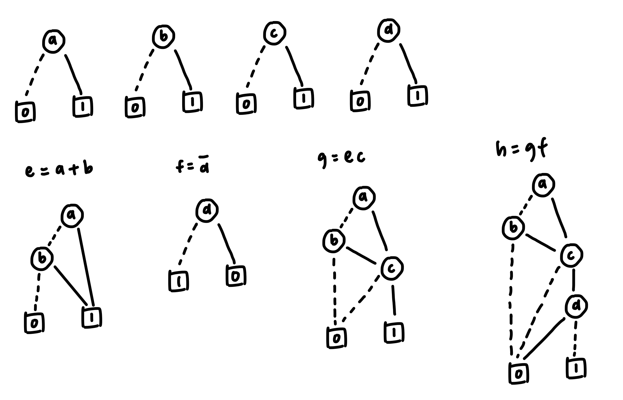
First, we have to convert every single input into a binary decision diagram (BDD). Then we convert the whole circuit into a Reduced-Ordered-Binary-Decision Diagram (ROBDD).
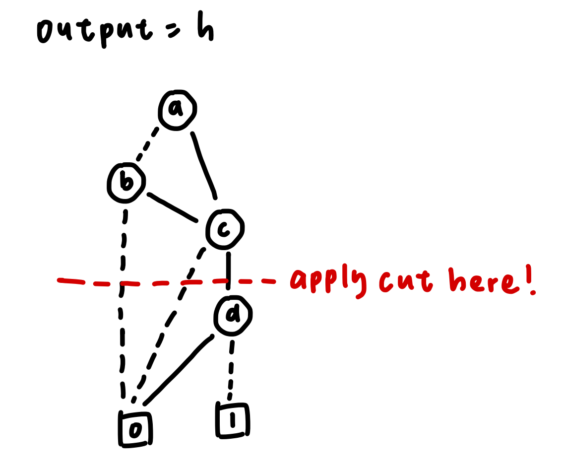
After that, we can do the cut according to our desired number of inputs in the LUT. In this case, we are trying to break down the logic circuit into a 3-input LUT, so we could apply the cut after node c.
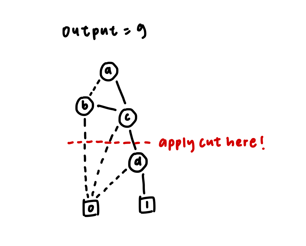
After that, we could create a 3-input look-up table (LUT) containing the possible signals of node a, node b and node c in the LUT.
| a | b | c | output |
|---|---|---|---|
| 0 | 0 | 0 | 0 |
| 0 | 0 | 1 | 0 |
| 0 | 1 | 0 | 0 |
| 0 | 1 | 1 | 1 |
| 1 | 0 | 0 | 0 |
| 1 | 0 | 1 | 1 |
| 1 | 1 | 0 | 0 |
| 1 | 1 | 1 | 1 |
As you can see, only [011, 101, 111] has an output of 1, which gives the signal to node d. Now, we could create another look-up table for the final output.
| output | d | null input (don’t cares) | final output |
|---|---|---|---|
| 0 | 0 | x | 0 |
| 0 | 1 | x | 0 |
| 1 | 0 | x | 0 |
| 1 | 1 | x | 1 |
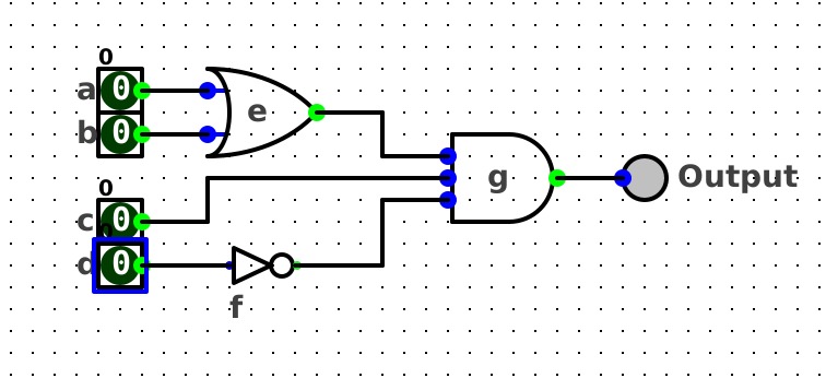
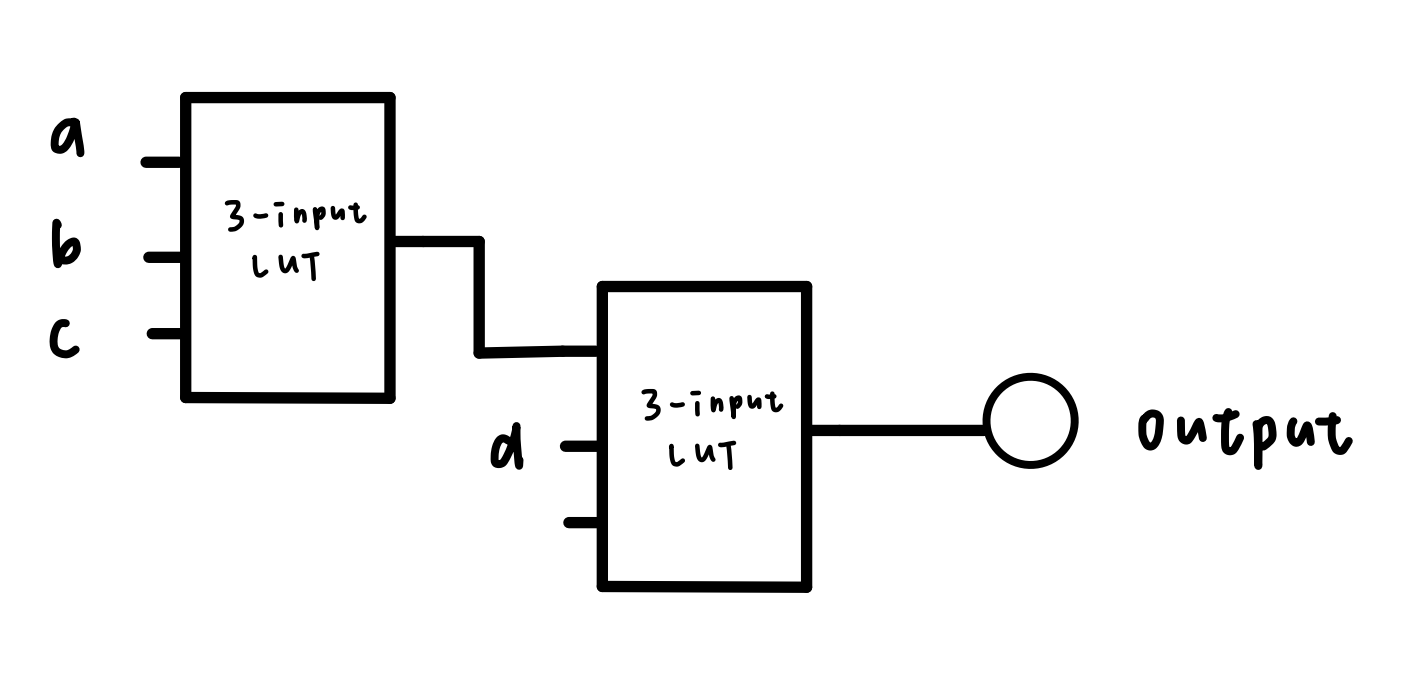
Finally, the logic circuit with LUT would look like:

To have a deeper understanding of the topic, here is another example:
Convert the boolean algebra below into a 3-input LUT circuit.f(a, b, c, d) = (a+b)cd'The logic circuit of the above boolean algebra looks like this:
As you can see, the above logic circuit has a 3-input AND gate; we could not do the decomposition with a logic gate with a number of inputs greater than 2. Therefore, we have to convert the logic circuit with every component having a number of inputs less than 2 before doing the decomposition.
The logic circuit after conversion is shown below:
Now, we convert every input into a binary decision diagram (BDD)and convert the whole circuit into a Reduced-Ordered-Binary-Decision Diagram (ROBDD).
In this case, we are trying to break down the logic circuit into a 3-input LUT, so we could apply the cut after node c.
After that, we could create a 3-input look-up table (LUT) containing the possible signals of node a, node b, and node c in the 3-input LUT.
| a | b | c | output |
|---|---|---|---|
| 0 | 0 | 0 | 0 |
| 0 | 0 | 1 | 0 |
| 0 | 1 | 0 | 0 |
| 0 | 1 | 1 | 1 |
| 1 | 0 | 0 | 0 |
| 1 | 0 | 1 | 1 |
| 1 | 1 | 0 | 0 |
| 1 | 1 | 1 | 1 |
Now, we could create another look-up table for the final output.
| output | d | null input (don’t cares) | final output |
|---|---|---|---|
| 0 | 0 | x | 0 |
| 0 | 1 | x | 0 |
| 1 | 0 | x | 1 |
| 1 | 1 | x | 0 |
Finally, the logic circuit with LUT would look like:
Coming dev plan
Modify quantr-logic to support converting the circuit into LUTs. The LUT library is in here. Added two buttons, one for converting the circuit into a 2-input circuit, second button is to generate everything we need in LUTs.

Author: Michelle

There are too many guys who claim they are industry leaders and tell teenagers their research is meaningless and not worth doing. As an ancestor, they don’t provide skill and money but rather keep bullshitting around teenagers. As revenge, an “avenger license” is needed, this license is based on Apache License version 2.0 with additional terms:
- Avenger license is only applicable in Hong Kong. For anyone outside Hong Kong, the Avenger license is the same as the Apache license version 2.0
- If he/she were a Hong Kong citizen and moved outside Hong Kong, they still applicable for this license
- If he/she says the project is not worth doing or has no chance of success, the Avenger license will block their 10-closest relationship people from using the software/hardware:
- Great-grandfather
- Grandfather
- Father
- Myself
- Son
- Grandson
- Great-grandson
- Colleague
- Wife
- Wife’s colleague
有太多人聲稱自己是行業領導者或前輩,並告訴青少年他們的研究毫無意義,不值得做。 作為前輩,他們不但不提供技能和金錢,而是不斷在青少年周圍胡言亂語。 作為報復,需要一個“復仇者許可證”,該許可證基於 Apache License 2.0 版,附加條款:
- Avenger牌照只適用於香港。 對於香港以外的任何人,Avenger 許可證與 Apache 許可證版本 2.0 相同
- 如果他/她是香港公民並移居香港以外地區,他們仍然適用此許可證
- 如果他/她說該專案不值得做或沒有成功的機會,Avenger 許可證將阻止他們關係最密切的十種人使用該軟體/硬體:
- 曾祖父
- 祖父
- 父親
- 我
- 兒子
- 孫子
- 曾孫
- 同事
- 妻子
- 妻子的同事
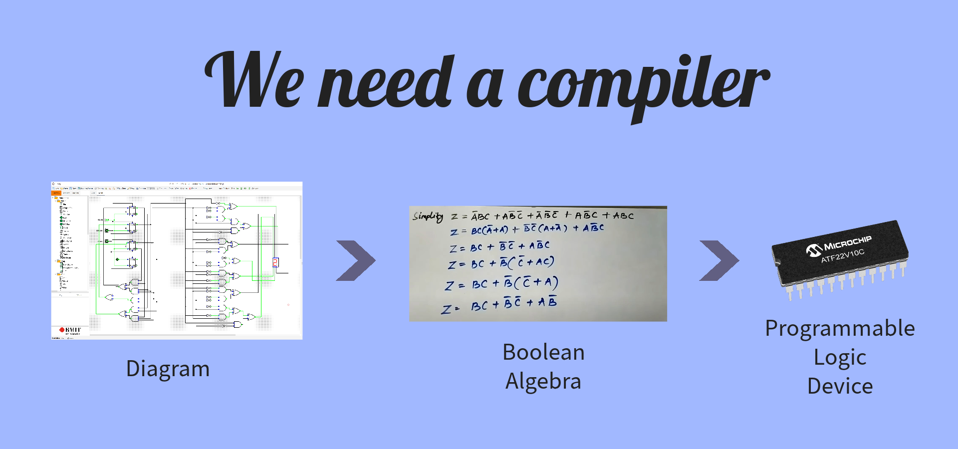
Initially, we were thinking of synthesizing our logic into FPGA, but most of the vendors don’t open their bitstream format, and hacking takes a huge amount of time. Now we have changed a new way: we synthesize our logic into PLD (programmable logic device), especially for CPLD or PAL.
Now we need a logic compiler, converting the diagram data structure which outputs from Quantr-Logic to boolean algebra, and compiles it into PLD format, which can be sent to the programmer to burn the logic.
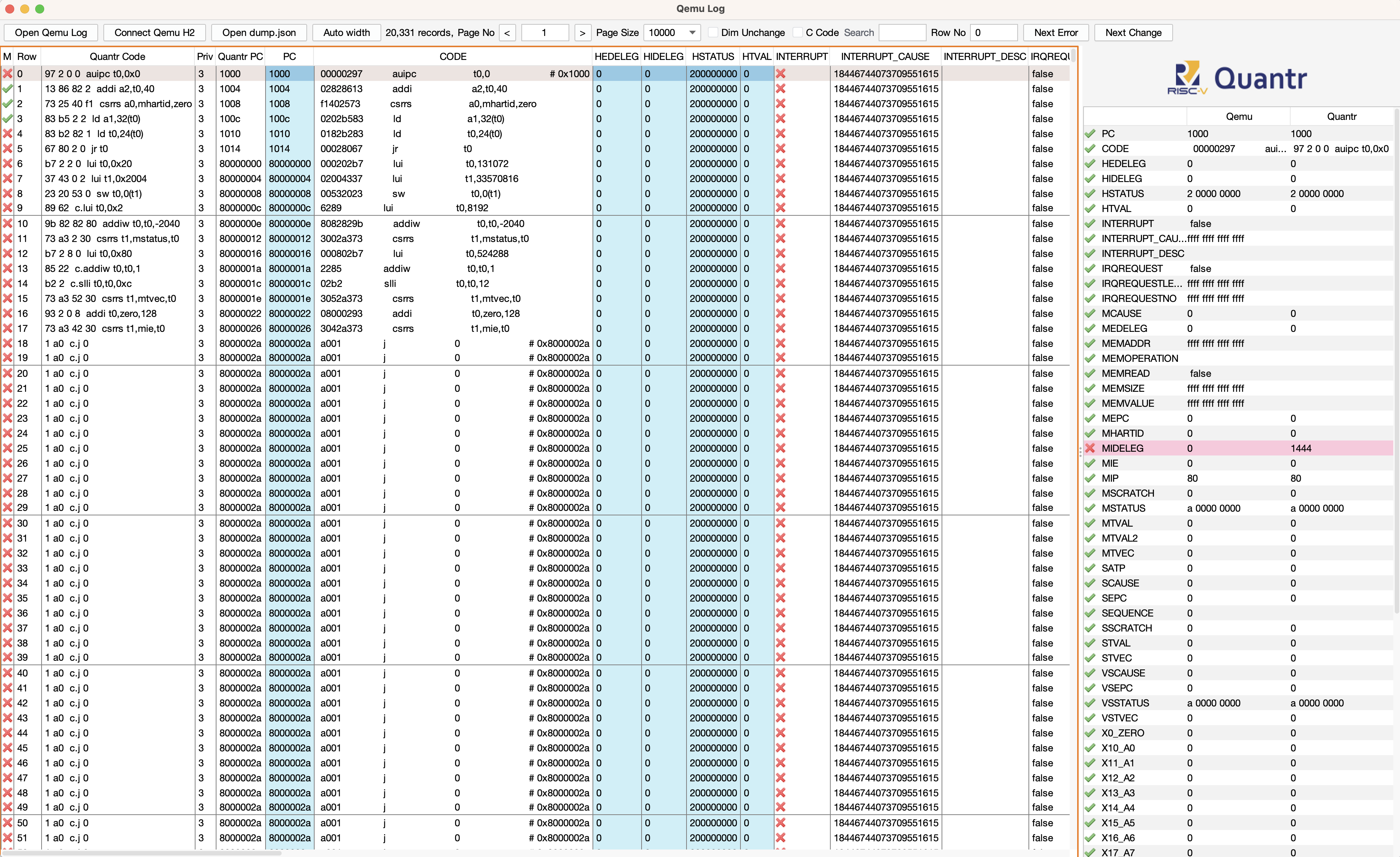
The principle is to generate two h2 database file, one from executing qemu, one from executing riscv-simulator
- Go to /Users/peter/workspace/riscv-simulator/src/test/resources/hk/quantr/riscv_simulator/elf/timer
- make run , then you have cpu.log
- run “java -jar ~/workspace/qemu-log-panel/target/qemu-log-panel-1.0-jar-with-dependencies.jar -f cpu.log -t” to convert cpu.log to database.mv.db, which is the h2 database file
- Setup riscv-simulator as
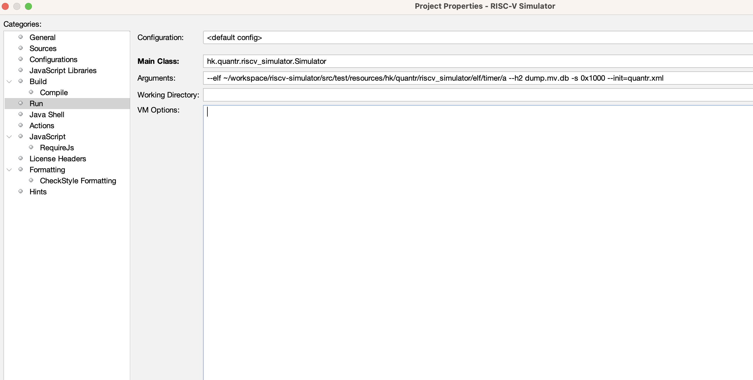
5. run it, then you got the “dump.mv.db” in riscv-simulator folder
6. Now you can run the qemu-log-panel
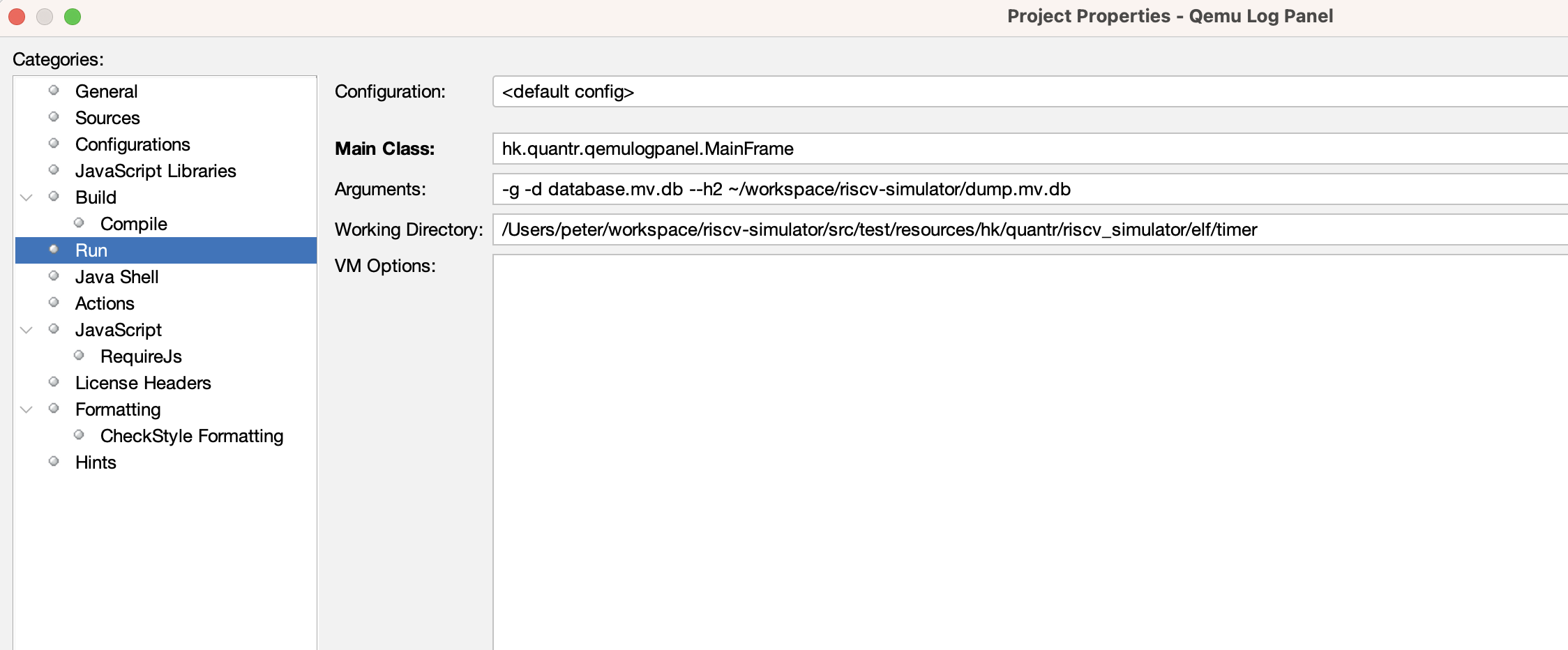
Then you see this
This year MUHK FYP, join if you are MUHK student. These are our past project:
https://www.hkmu.edu.hk/st/engsc/fyp/2021-22/risc-v-simd-simulation/
These are the OUHK FYP projects, student co-work with us on RISC-V topics. One of the project listed on OUHK website https://www.hkmu.edu.hk/st/engsc/fyp/2021-22/risc-v-simd-simulation/
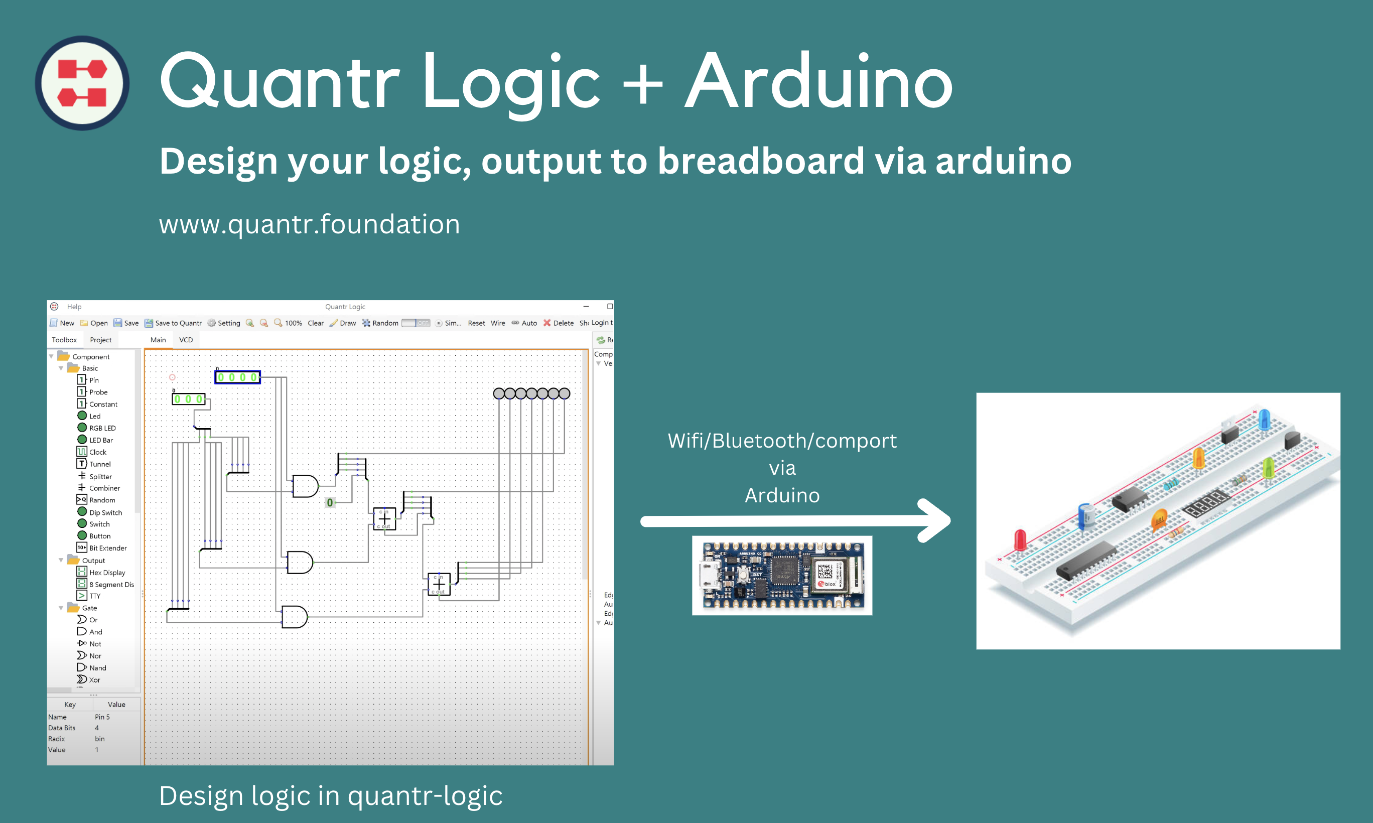
It would be super fun to connect Quantr-Logic to breadboard, we need a media to do that and we think of Arduino. We will build the connector using Arduino boards, lets see how funny it is.