After doing much online research and reading many reference books, our team has figured out a way to convert logic circuits into look-up tables (LUT).
Overview
To convert a logic circuit into LUTs, first we should convert them to 2-input logic gates. The decomposition could only be done with two or fewer input logic gates. After that, we have to convert the diagram to a reduced ordered binary decision diagram (ROBDD). Thus, breaking down the logic circuit into the desired number of inputs in the LUT.
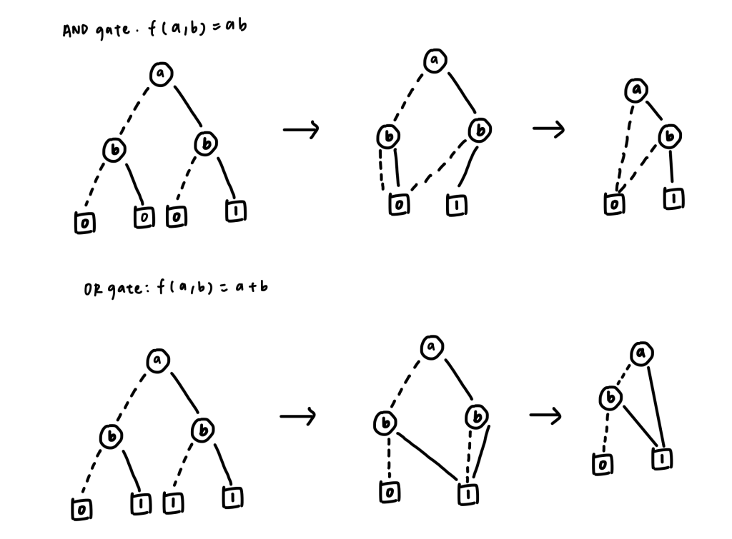
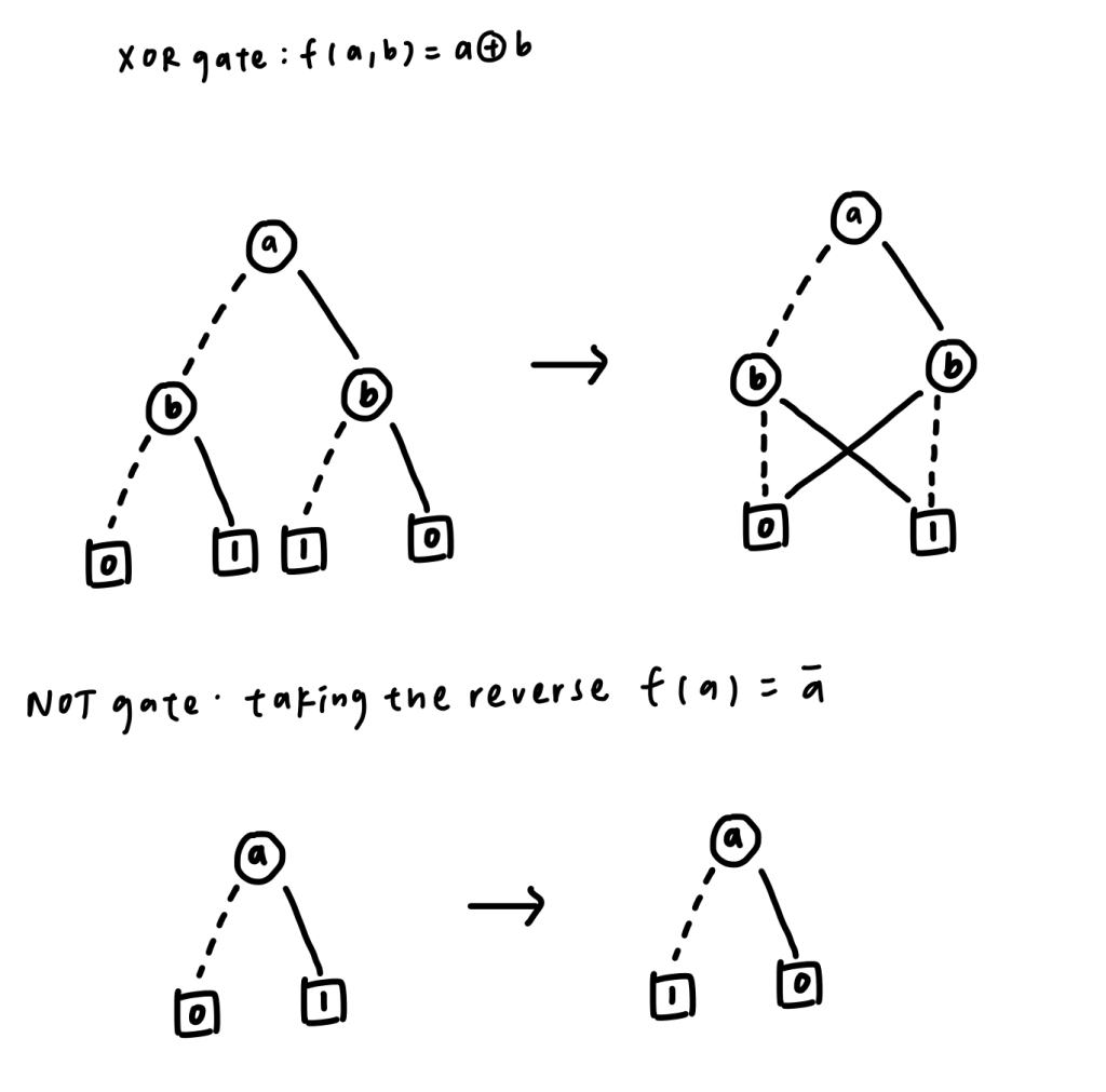
For converting the boolean algebra into a binary decision diagram (BDD), there are certain formulas for converting different logic gates. We could compose the boolean algebra with AND gates, OR gates, XOR gates, and NOT gate. They are listed below:
Fig 1. Convert boolean algebra (or , and) to BDD and BDD to ROBDD
Fig 2. Convert boolean algebra (xor, not) to BDD and BDD to ROBDD
To illustrate how to do the decomposition, here is a simple example:
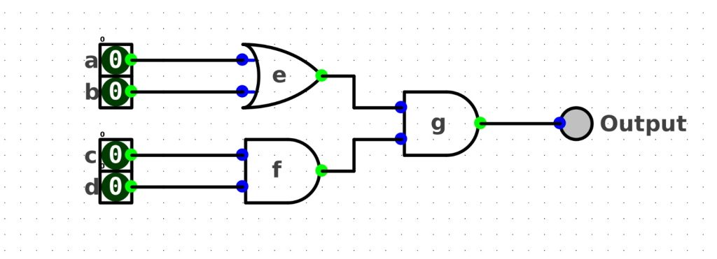
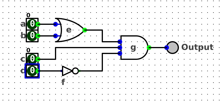
Convert the boolean algebra below into a 3-input LUT circuit.f(a, b, c, d) = (a+b)•cdThe logic circuit of the above boolean algebra looks like this:
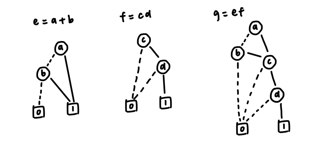
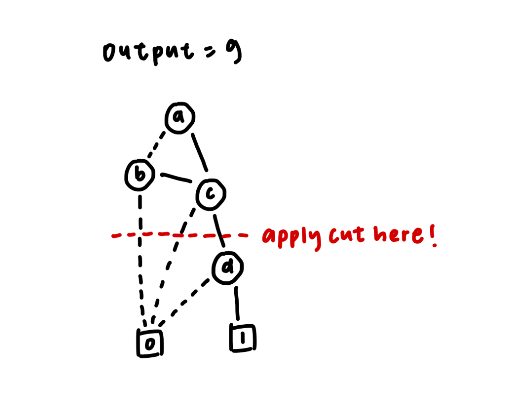
First, we have to convert every single input into a binary decision diagram (BDD). Then we convert the whole circuit into a Reduced-Ordered-Binary-Decision Diagram (ROBDD).
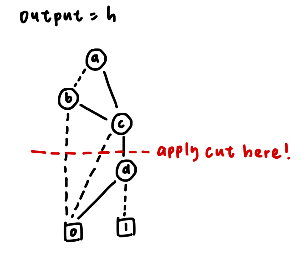
After that, we can do the cut according to our desired number of inputs in the LUT. In this case, we are trying to break down the logic circuit into a 3-input LUT, so we could apply the cut after node c.
After that, we could create a 3-input look-up table (LUT) containing the possible signals of node a, node b and node c in the LUT.
| a | b | c | output |
|---|---|---|---|
| 0 | 0 | 0 | 0 |
| 0 | 0 | 1 | 0 |
| 0 | 1 | 0 | 0 |
| 0 | 1 | 1 | 1 |
| 1 | 0 | 0 | 0 |
| 1 | 0 | 1 | 1 |
| 1 | 1 | 0 | 0 |
| 1 | 1 | 1 | 1 |
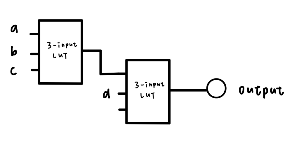
As you can see, only [011, 101, 111] has an output of 1, which gives the signal to node d. Now, we could create another look-up table for the final output.
| output | d | null input (don’t cares) | final output |
|---|---|---|---|
| 0 | 0 | x | 0 |
| 0 | 1 | x | 0 |
| 1 | 0 | x | 0 |
| 1 | 1 | x | 1 |
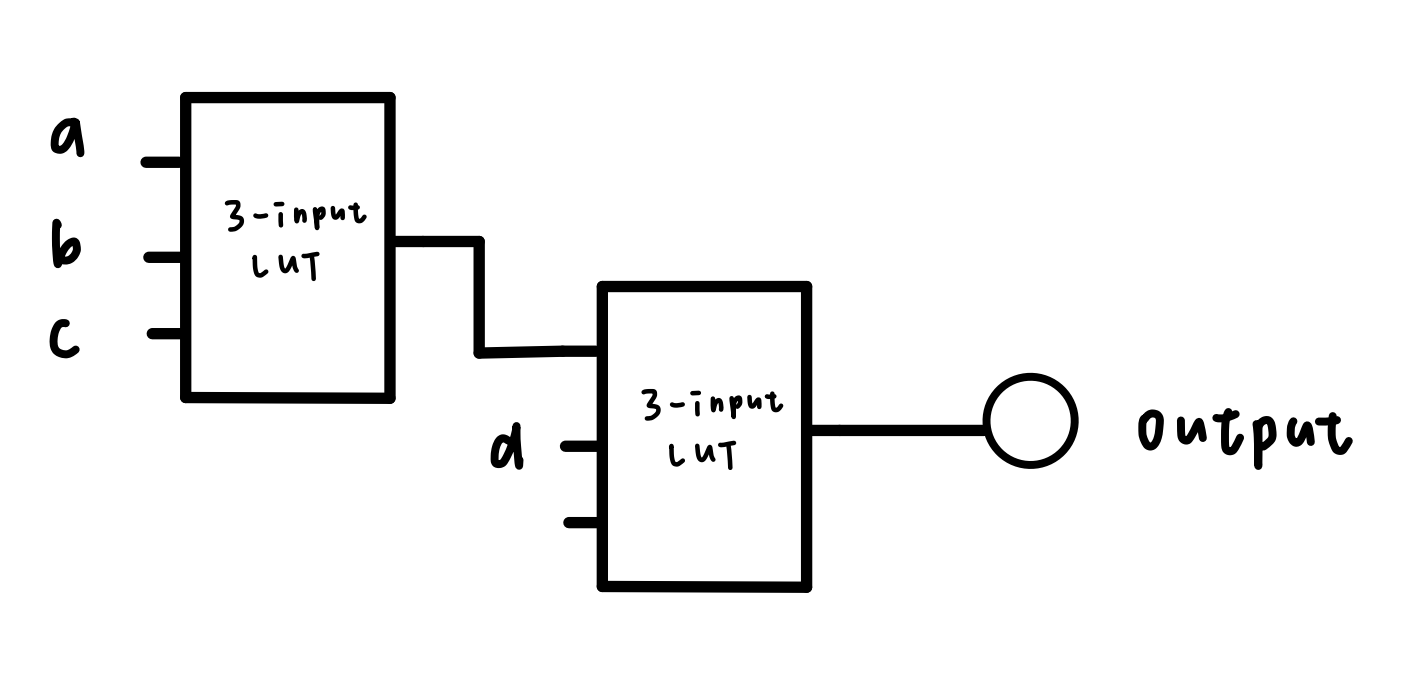
Finally, the logic circuit with LUT would look like:
To have a deeper understanding of the topic, here is another example:
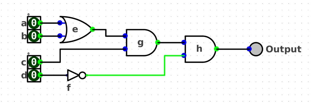
Convert the boolean algebra below into a 3-input LUT circuit.f(a, b, c, d) = (a+b)cd'The logic circuit of the above boolean algebra looks like this:
As you can see, the above logic circuit has a 3-input AND gate; we could not do the decomposition with a logic gate with a number of inputs greater than 2. Therefore, we have to convert the logic circuit with every component having a number of inputs less than 2 before doing the decomposition.
The logic circuit after conversion is shown below:
Now, we convert every input into a binary decision diagram (BDD)and convert the whole circuit into a Reduced-Ordered-Binary-Decision Diagram (ROBDD).
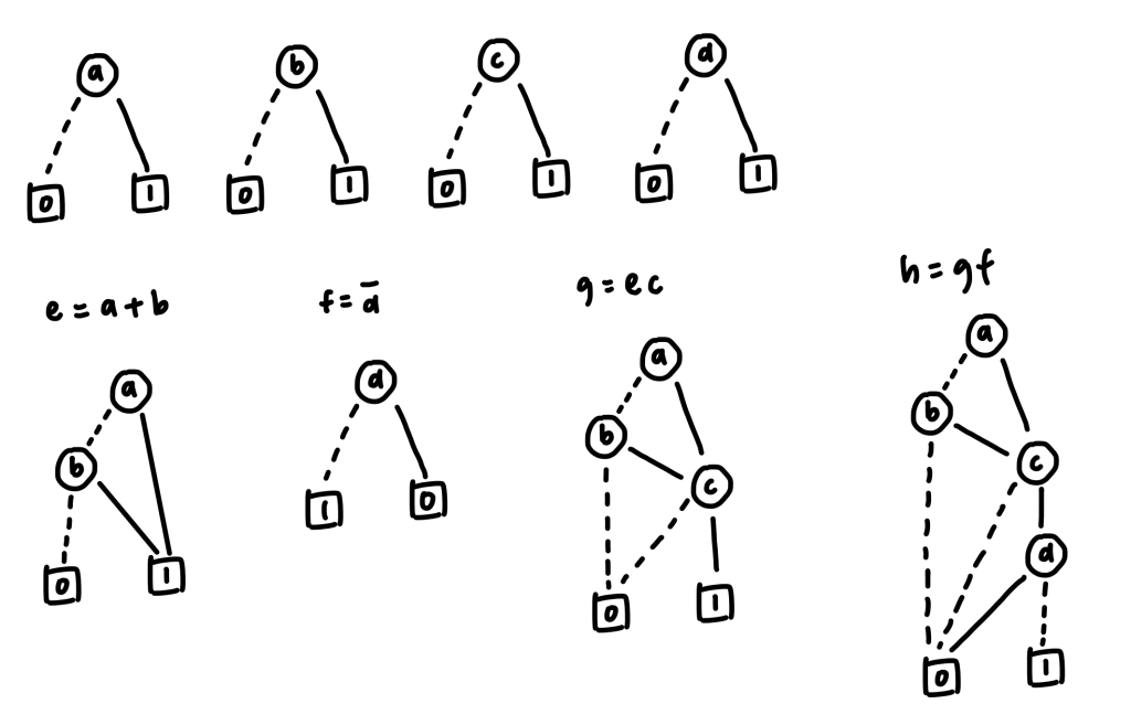
In this case, we are trying to break down the logic circuit into a 3-input LUT, so we could apply the cut after node c.
After that, we could create a 3-input look-up table (LUT) containing the possible signals of node a, node b, and node c in the 3-input LUT.
| a | b | c | output |
|---|---|---|---|
| 0 | 0 | 0 | 0 |
| 0 | 0 | 1 | 0 |
| 0 | 1 | 0 | 0 |
| 0 | 1 | 1 | 1 |
| 1 | 0 | 0 | 0 |
| 1 | 0 | 1 | 1 |
| 1 | 1 | 0 | 0 |
| 1 | 1 | 1 | 1 |
Now, we could create another look-up table for the final output.
| output | d | null input (don’t cares) | final output |
|---|---|---|---|
| 0 | 0 | x | 0 |
| 0 | 1 | x | 0 |
| 1 | 0 | x | 1 |
| 1 | 1 | x | 0 |
Finally, the logic circuit with LUT would look like:
Coming dev plan
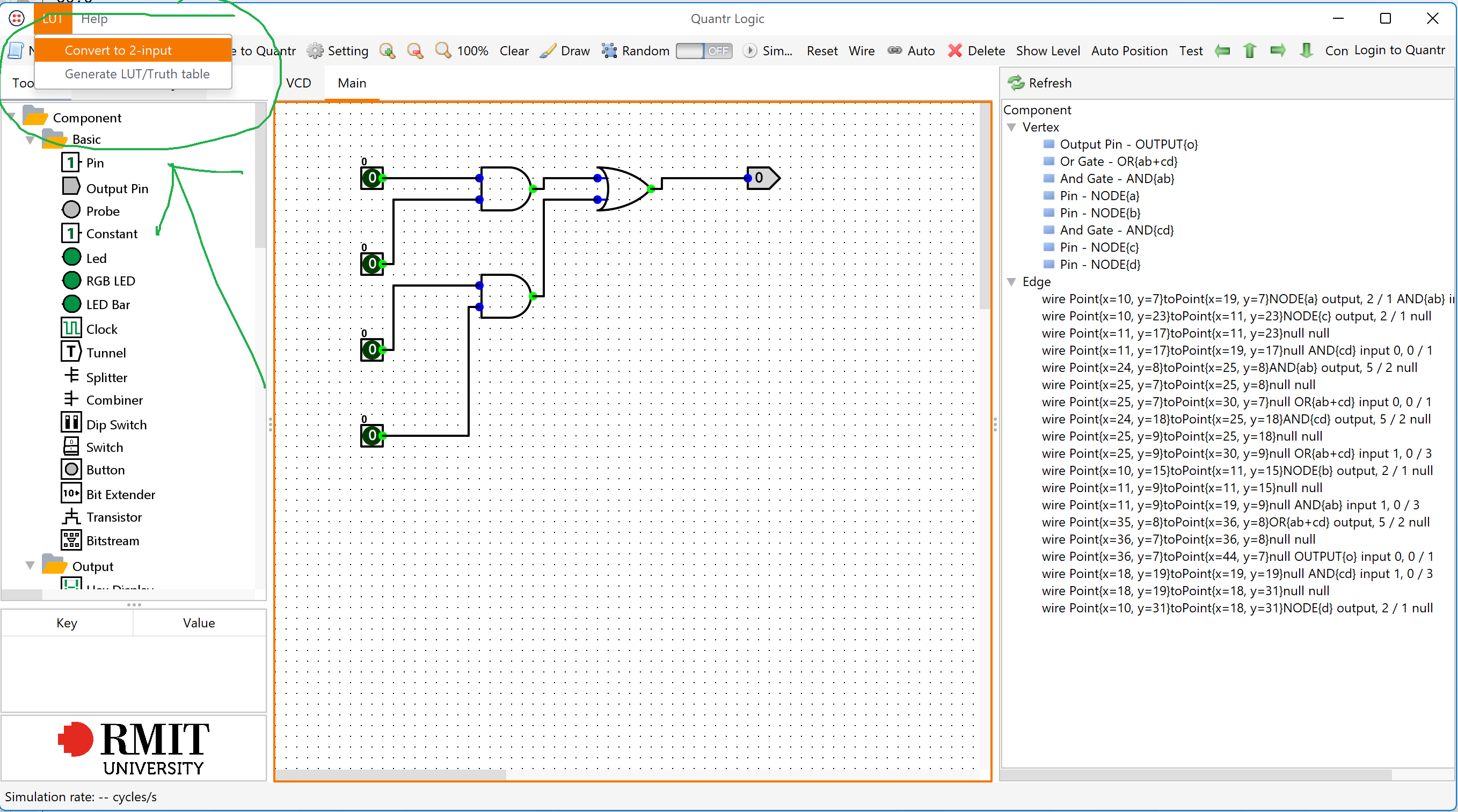
Modify quantr-logic to support converting the circuit into LUTs. The LUT library is in here. Added two buttons, one for converting the circuit into a 2-input circuit, second button is to generate everything we need in LUTs.

Author: Michelle
